Data Feeders
1. Why we used them?
We have already described the processing element. Now, since we are using a 4×4 systolic array, a total of 16 processing elements will be used.
- Each processing element takes 8-bit input.
- However, we have 7 elements in a row/column (as per the systolic array architecture).
- This makes it 7 × 8 = 56 bits.
A simple solution is to use data feeders, in which we feed 56-bit row/column data and get 8-bit elements by shifting them one by one, which are then fed to the respective registers.
2. PinOut
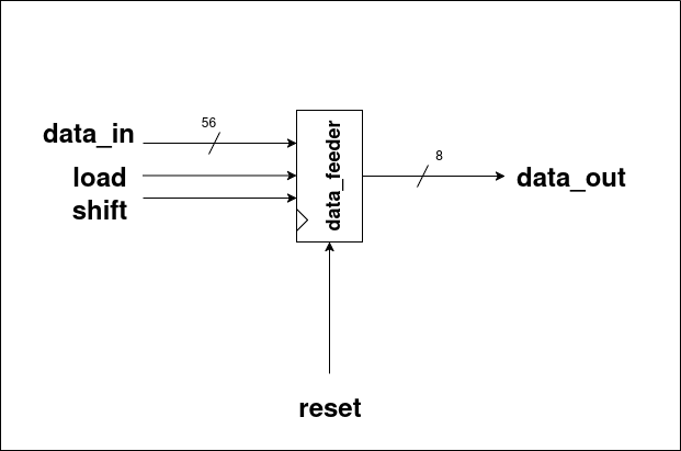
Inputs:
- data_in – 56-bit input row/column data.
- load – Load signal to initialize the feeder.
- shift – Shift signal to move data one element at a time.
- reset – Resets the internal state of the feeder.
Outputs:
- data_out – 8-bit output element, fed to the respective registers.
3. Design Diagram
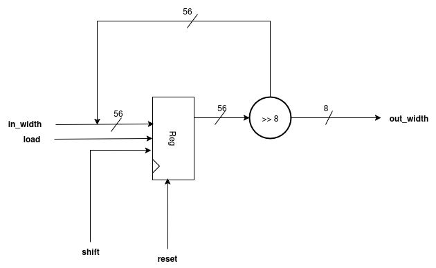
Explanation
- The
in_width(i.e.,data_in) is stored in a register wheneverloadis high andresetis off. - When the shift signal is high, the register shifts data from the Most Significant Bit (MSB).
- This process produces seven 8-bit chunks, which are then fed to the Processing Elements as individual elements of a row/column.
- These seven 8-bit chunks form the out_width, which corresponds to
data_out.
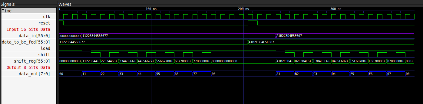
Simulations: