MAC Unit
1. PinOut
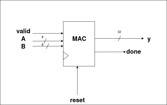
Inputs
- Takes the following as inputs:
- valid
- A (8-bit element of matrix)
- B (8-bit element of matrix)
- reset
Outputs
- Provides the following as outputs:
- y → 32-bit result
- done → 1-bit signal which goes high whenever
yis valid, indicating that the MAC unit has completed the operation.
2. Design Diagram
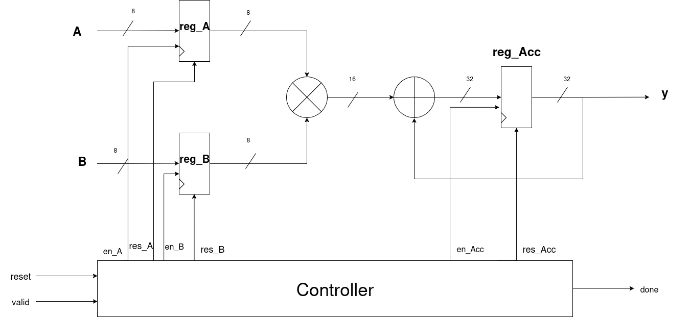
Explanation
- First of all, the user enters elements A and B.
- As soon as reset is off and valid becomes high:
en_Aanden_Bgo high.- The user-entered A and B values are stored in their respective registers:
reg_Aandreg_B. - Then:
- Both values are multiplied.
- The result is added to the previous result (principle of MAC).
- A register named reg_Acc stores the result whenever
en_Accgoes high. - (When
en_Accgoes high will be explained in the STG section.) - Since both input elements are 8 bits:
- Multiplication produces a 16-bit result.
- This result is padded to 32 bits → giving output
yas 32 bits. - As soon as the result
yis obtained, the done signal goes high.
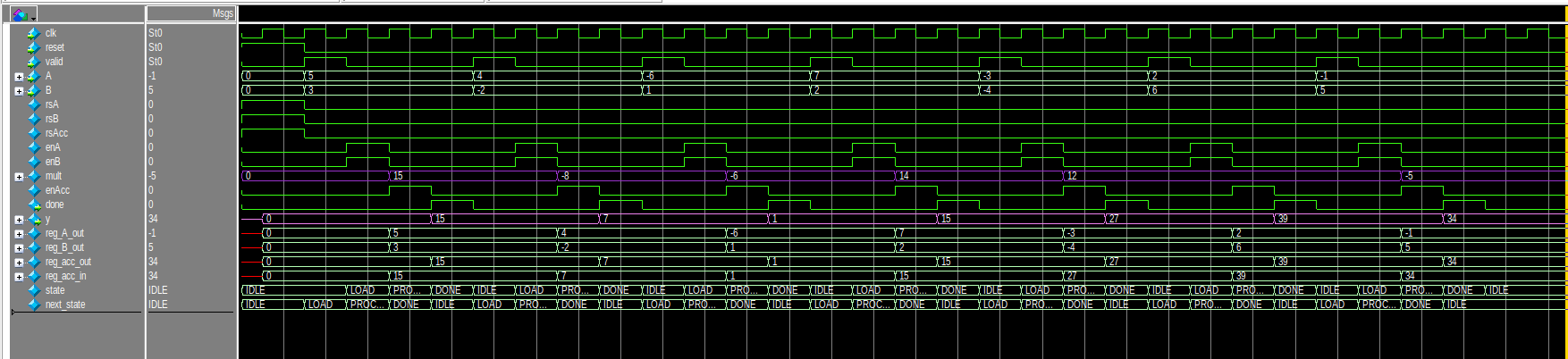
Simulations:
3. Register Design
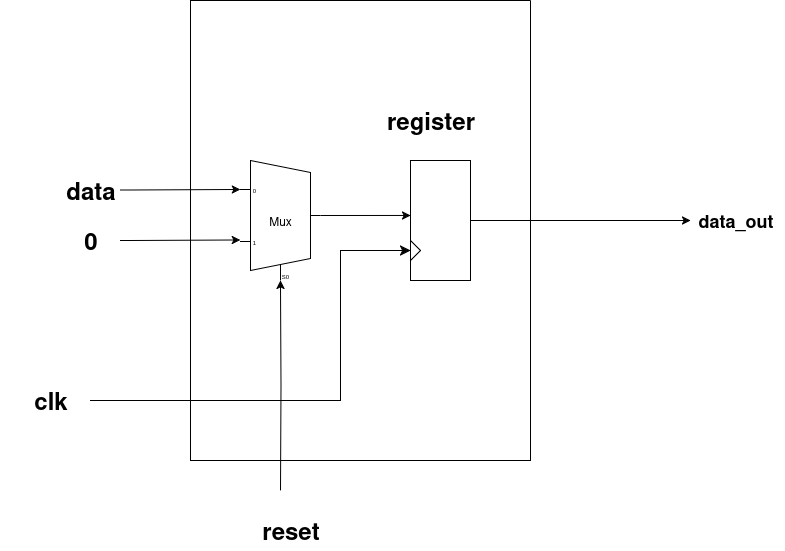
- This is the general register design used for all the registers in our system.
- First, a 2×1 MUX is used, whose output is stored into a register.
- The selector pin of the MUX is
reset. - Behavior:
- When reset = 0 (off) → The MUX selects input data, which is stored in the register. The corresponding
data_outis available in the next cycle. - When reset = 1 (high) → The MUX selects zero, and hence the register outputs
0asdata_out.
4. State Transition Graph (STG)
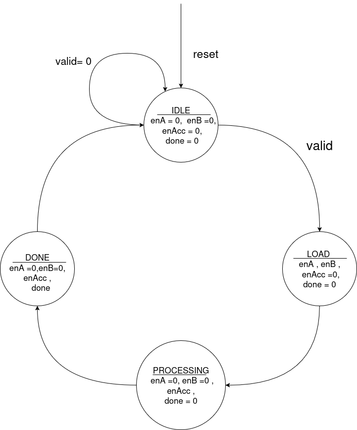
Explanation
I. IDLE
- Whenever reset = 1, the system enters the IDLE state:
- All register enables are low.
done = 0.- It remains in IDLE if
valid = 0. - When a valid signal is received, it transitions to the LOAD state.
II. LOAD
- In this state:
- Enables of reg_A and reg_B go high → user inputs are stored in
reg_Aandreg_B. - reg_Acc is still off (no computation yet).
done = 0since no result is available yet.- Next, it transitions to the PROCESSING state.
III. PROCESSING
- In this state:
- reg_A and reg_B enables go low (to hold current inputs and avoid taking new ones).
- reg_Acc enable goes high → computation starts, and result is stored in the accumulator.
done = 0since computation is still ongoing.- Next, it transitions to the DONE state.
IV. DONE
- In this state:
- en_A and en_B remain off.
- en_Acc stays on.
- The done signal = 1 → indicating completion of computation.
- Finally, it transitions back to IDLE, and the cycle continues.