PROCESSING ELEMENT (PE)
1.PinOut:
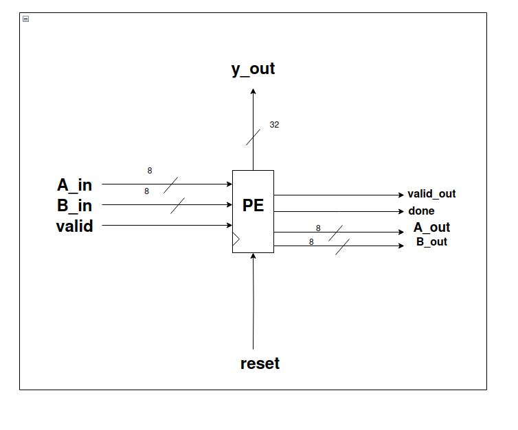
Inputs:
- valid, reset, A_in, B_in as inputs.
- A_in, B_in are 8-bit signals.
Outputs:
- A_out, B_out, done, valid_out, y_out.
- A_out, B_out are 8-bit signals.
- done goes high whenever the MAC operation completes.
- valid_out goes high whenever the overall PE operation completes.
- y_out is the 32-bit output of the PE.
2. Design Diagram
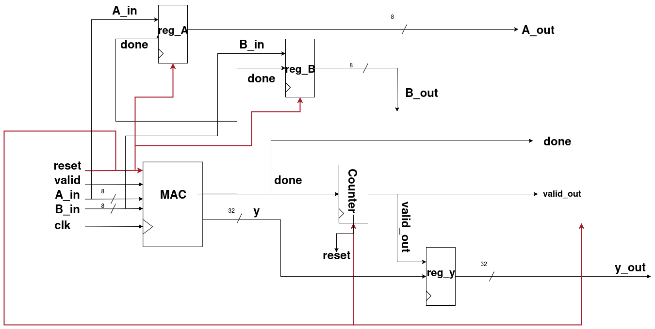
Explanation:
- Step 1:
A_in,B_in,valid, andresetgo to the MAC unit and process the same way as explained earlier. - Step 2: From the MAC unit, we get
yanddoneas outputs. doneindicates that the MAC process has been completed.- This
donesignal is passed through a counter (design explained below). - When the counter registers 7 occurrences of
done, thevalid_outflag becomes high, showing that the PE’s computations are complete. - Step 3: The
valid_outalso connects to a register. When we get 7 outputs ofyfrom the MAC unit, it confirms that the PE’s calculations are finished, and finally,y_out(32 bits) is produced.
Why count 7 times?
- In the Systolic Array Architecture, after padding, the last row and last column expand into 7 elements:
- 4 actual elements
- 3 padded zeros
- Therefore, we must count 7
donesignals to ensure that the row/column computation has finished correctly.
Role of A_out and B_out
- Whenever the
donesignal goes high,A_inandB_inare stored inreg_Aandreg_B. - These values then propagate outward as
A_outandB_out.
Why are A_out and B_out needed?
- In the systolic array, each PE must process 7 elements per row/column.
- In a 4×4 systolic array, there are 16 Processing Elements (PEs) working in parallel.
- To enable this parallel pipelined computation, each PE forwards
A_outandB_outto its neighbors. - This design ensures faster computations by reducing the number of cycles required.
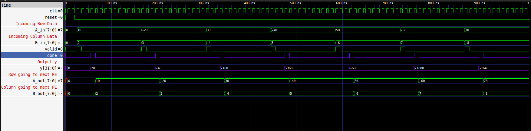
Simulations:
Counter
I. PinOut:
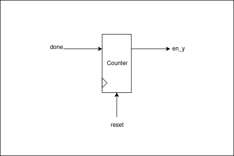
Inputs:
- reset – Resets the counter.
- done – Input pulse that needs to be counted.
Outputs:
- en_y – Goes high when the counter completes 7 counts.
II. Design Diagram
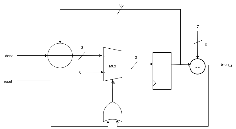
Explanation
- The input signal (
done) is added to the previous result. - The previous result is selected by a Mux.
- The selector pin of the Mux is driven by the OR of
resetanden_y. - If
resetis high oren_yis high (count complete), the Mux passes zero. - Otherwise, it passes the actual input to be stored in the register.
- A comparator checks each result.
- When the count reaches 7, the comparator output goes high, raising
en_y.