Systolic Array
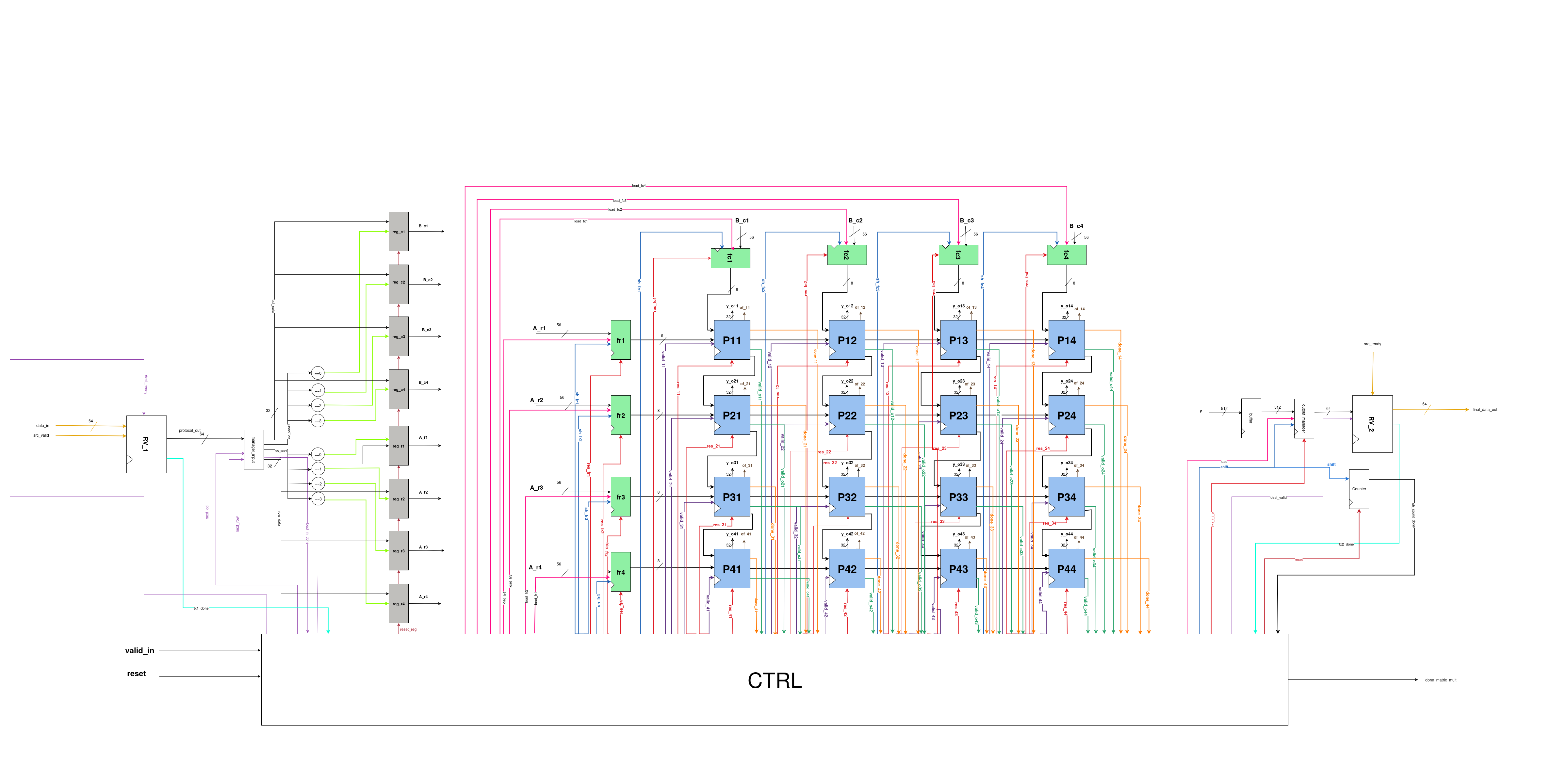
Main Parts of the Systolic Array
Our final Systolic Array consists of three main parts:
- Input Datapath
- Systolic Top
- Output Datapath
EXPLANATION
1. Input DataPath
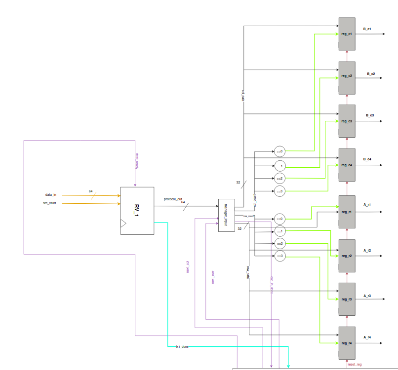
Explanation
- The user provides a 64-bit input, which first enters the Ready–Valid Protocol (RV_1).
- When both
src_validanddest_readyare high, handshaking occurs, producing: protocol_out→ the same 64-bit input-
tx1_done→ generated in the next cycle -
The 64-bit
protocol_outis passed to the Output Manager, where it is split into two 32-bit parts: [63:32]→ row data-
[31:0]→ column data -
Row_count and col_count act as enables for registers
reg_riandreg_cj(i,j = 0 to 3) -
First row/column:
-
row_count = col_count = 0→ stored inreg_r1andreg_c1 -
Subsequent rows/columns:
- When
next_rowandnext_colgo high,row_countandcol_countincrement. -
Values are stored in
reg_r2/reg_c2,reg_r3/reg_c3, andreg_r4/reg_c4. -
When
row_countandcol_count = 3, all four rows and columns are captured. -
load_in_donesignal is asserted → indicates all inputs have been successfully loaded -
Registers holding the values:
- Rows:
reg_r1,reg_r2,reg_r3,reg_r4 -
Columns:
reg_c1,reg_c2,reg_c3,reg_c4 -
56-bit outputs generated from registers:
- Rows:
A_r1,A_r2,A_r3,A_r4 -
Columns:
B_c1,B_c2,B_c3,B_c4 -
These values are finally fed into the data feeders of the Systolic Array.
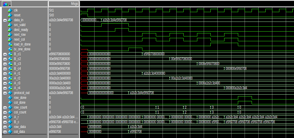
Simulations
2. Systolic Top
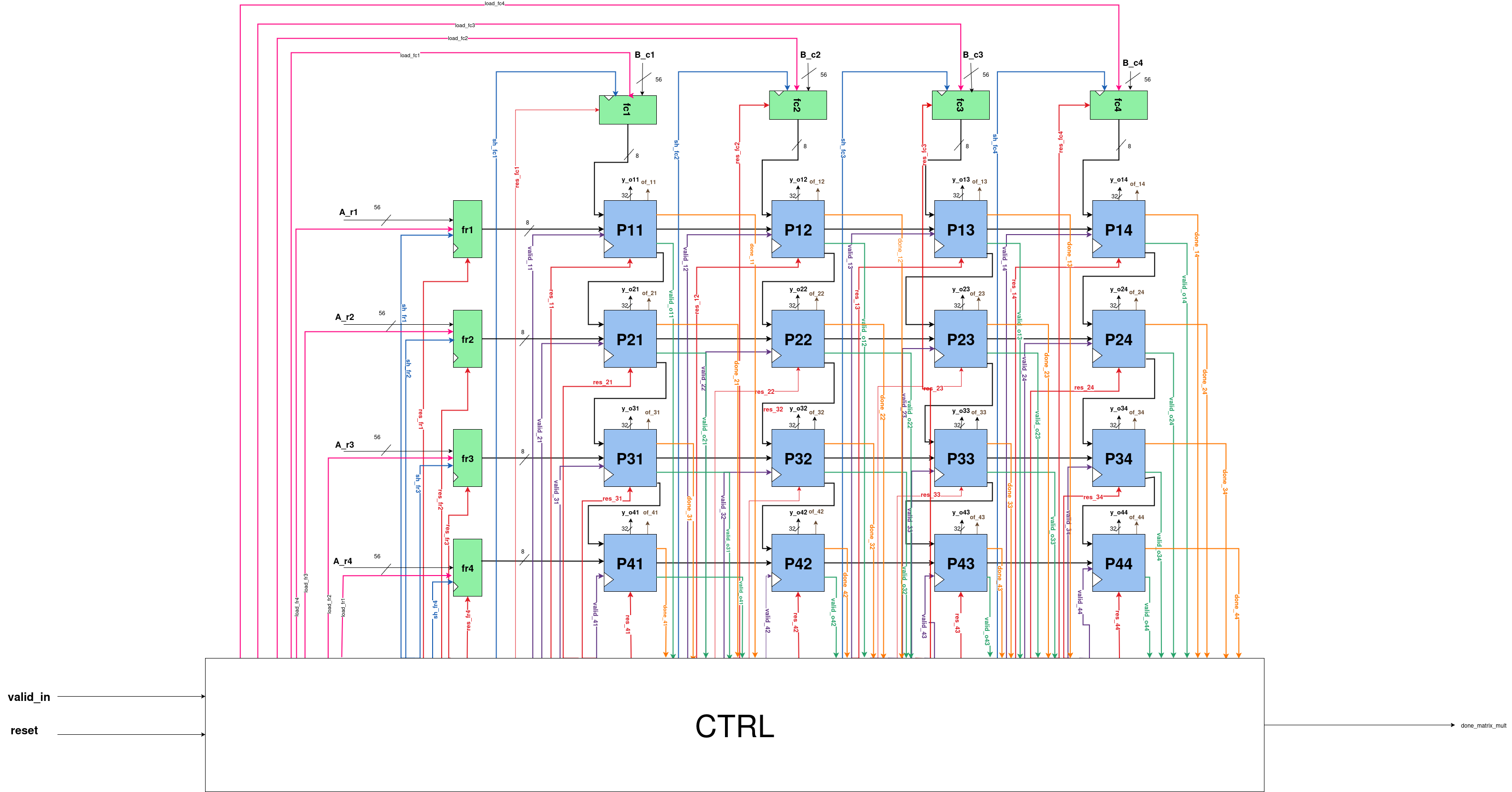
Explanation
- The four rows and four columns are fed into the data feeders, which pass them to the Processing Elements (PEs) as described earlier.
- Each PE produces a 32-bit output (
y_out). - Using a 4×4 systolic array, there are 16 PEs, resulting in a combined output of:
16 × 32 = 512 bits- This output is referred to as
y. - The 512-bit
yis then passed to the Output Datapath, where it is organized into eight 64-bit chunks, forming the final output. (Because64 × 8 = 512)
3. Output DataPath
Explanation
- The 512-bit
yfrom the Systolic Top is first stored in a buffer (simple register), which outputs the stored value in the next cycle. -
This 512-bit data is then sent to the Output Manager, where it waits for the load signal.
-
When load is asserted:
- The first 64 bits (from the MSB side) are sent to the Ready–Valid Protocol (RV_2).
-
When both
dest_validandsrc_readyare high in RV_2, handshaking occurs:final_data_out→ first 64-bit output chunktx2_done→ asserted to indicate successful transfer
-
After the first
final_data_out: - The shift signal from the Output Manager is asserted.
- The next 64-bit chunk is shifted out and sent to RV_2.
-
Handshaking occurs again → second 64-bit
final_data_outwithtx2_done. -
This process continues:
- A total of 7 shifts occur → 8 final outputs of 64 bits each.
-
Since
8 × 64 = 512, the entire Systolic Array output is successfully transferred. -
The 7 shift events are monitored by a Counter:
- Counts up to 7 shifts.
- Once all shifts are completed,
sh_count_doneis asserted → indicates entire computation and output transfer complete.
Simulations
COUNTER
PinOut
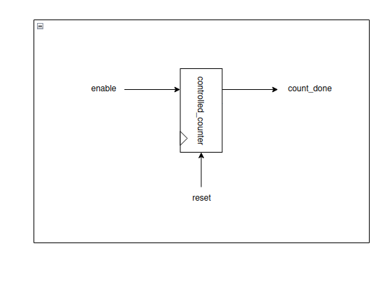
Inputs:
- enable – Starts the counting process.
- reset – Resets the counter to its initial state.
Outputs:
- count_done – Goes high when counting is complete.
Design Diagram
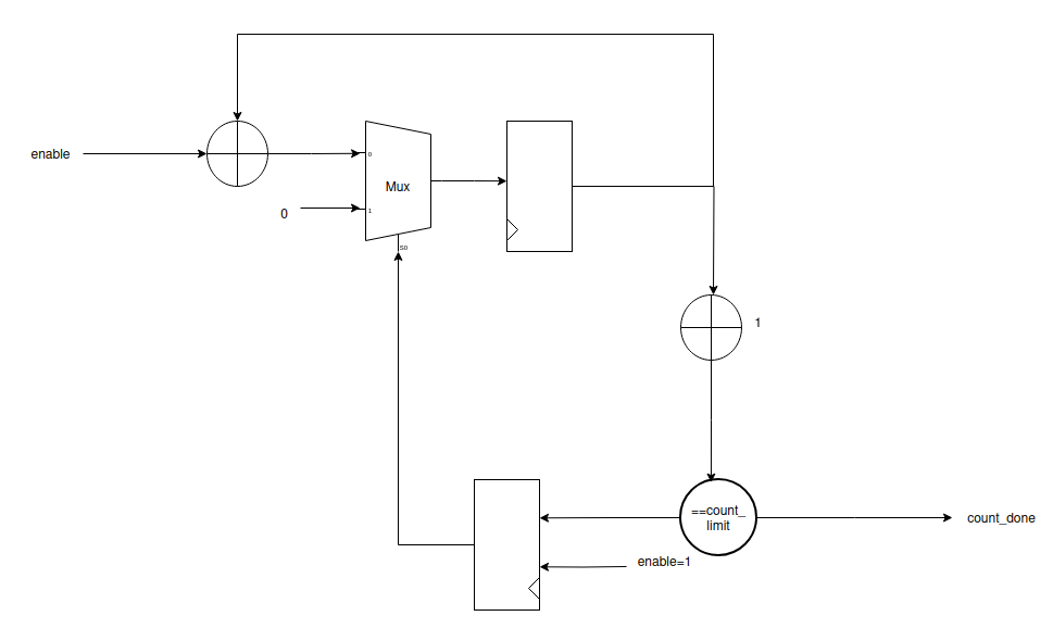
Explanation
Reset Phase
- When
rst = 1: - The counter (
count) is cleared to 0. count_donesignal is also cleared to 0.
Normal Operation (when rst = 0)
- On every posedge of clk, the counter checks the
enablesignal: - If
enable = 0→ counter holds its current value (no change). - If
enable = 1:- The counter increments by 1.
- While
count < count_limit - 1: - Only
countupdates count_doneremains 0- When
count = count_limit: count_doneasserts (1) for one clock cycle- The counter immediately resets back to 0
Key Behavior
- Counts clock cycles when enabled.
- After completing
count_limitcycles, it raises a 1-cycle done pulse (count_done). - The process repeats as long as
enableremains asserted.
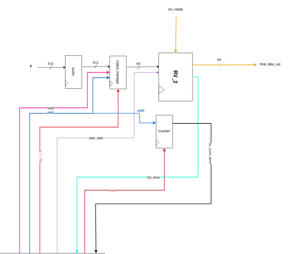
FINAL SYSTOLIC ARRAY
Design Diagram
We have connected all three main parts to get the overall final Systolic Array as shown below:
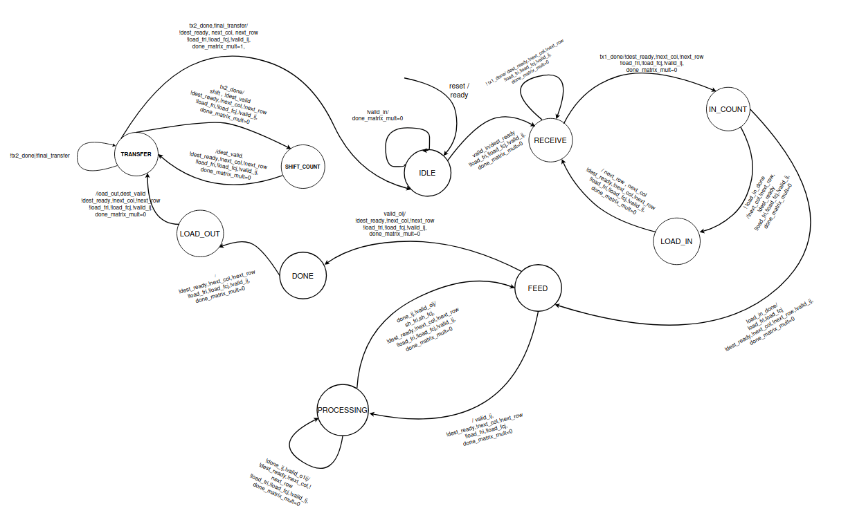
State Transition Graph (STG) of Controller
Explanation of States
I.IDLE:
- In this state, the processor is waiting for the valid_in signal.
- done_matrix_mult is 0 in this state.
II.RECEIVE:
- We reach this state when we get valid_in in the IDLE state.
- The dest_ready is set and we are waiting for a ready/valid handshake to occur.
- The handshake will occur when we receive the src_valid. It will be indicated by the tx1_done signal.
- When we receive the tx1_done signal, we will transition to the IN_COUNT state, else we will stay in RECEIVE state.
III.IN_COUNT:
- In this state, the dest_ready is set to 0.
- This state is meant to count the number of tx1_done signals after the first transition.
- It allows the data to be arranged for loading into the appropriate registers.
IV.LOAD_IN:
- While the load_in_done sigal is not set, we will move into this state. Meaning that control only moves into this state if the loading operation is incomplete.
- In this state, we wait for a cycle so that values get loaded into the appropriate registers.
- Then we unconditionally move back to the RECEIVE state for further data.
- During this transition to the RECEIVE state, it will set next_row and next_col to 1.
V.FEED:
- When the load_in_done signal is high in the IN_COUNT state, we transition into this state.
- In this state, all the load signals of the data feeders are set to 1, and hence it loads in the values and gives out 8-bits (MSBs) of data.
- After feeding, it unconditionally moves into the processing state, given that valid_o flag is not set.
- If the valid_o flag is set, we move to the DONE state.
VI.PROCESSING:
- In this state we wait till the done signals are set.
- The done signal will indicate the completion of a partial product.
- After receiving done signal, we move back to the FEED state.
- While moving into the FEED state, we set the shift signals of the feeders to 1 for a cycle, so that new elements are available to be fed into the chip.
VII.DONE:
- This state indicates the exit of the control from the systolic array and transitions into the LOAD_OUT state unconditionally.
- While doing so, it causes the buffer to be store the value of the computed product.
VIII.LOAD_OUT:
- This state transitions into the TRANSFER state unconditionally.
- While this transition, it will set the load of the final feeder to 1 and also set the dest_valid.
IX.TRANSFER:
- In this state we are waiting for the ready/valid handshake to occur.
- The handshake only happens when the src_ready signal is received.
- When it will occur, we will get the tx2_done signal. And we will transition into the SHIFT_COUNT state. During that transition, shift of the datafeeder will be set to 1 for a cycle. The dest_valid is set to 0.
- Until we get the tx2_done signal, the control will stay in this state.
- When we get tx2_done signal and also the final_transfer signal, the control jumps back to idle, setting matrix_mult_done to 1 for a cycle, indicating that the final element has been transferred.
- It also sets next_row and next_col to 1 in order to reset by overflowing their respective counters.
X.SHIFT_COUNT:
- This state transitions back into the TRANSFER state unconditionally.
- The dest_valid is set to 1 during transition.